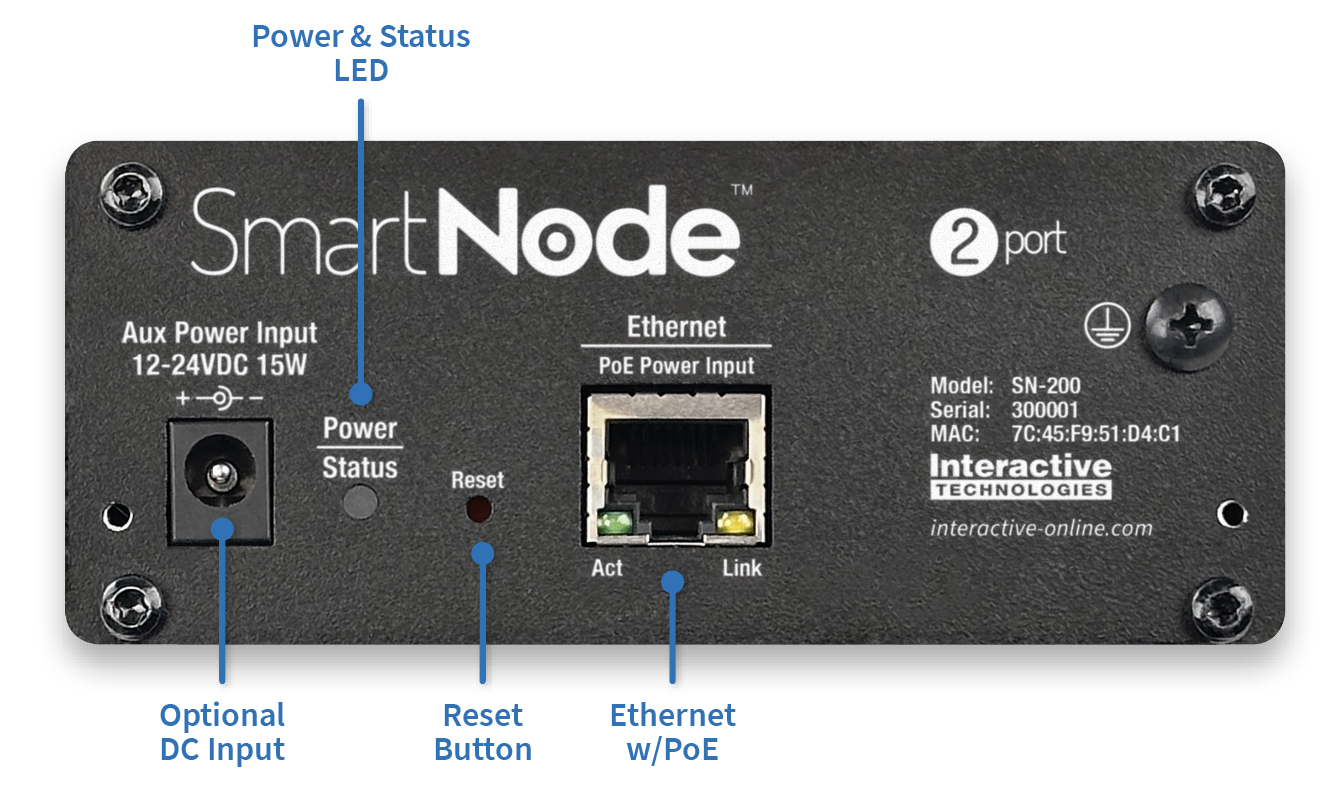
Front Panel
|
Power & Status LED |
This LED illuminates when power is on. The indicator displays different colors/patterns depending on operational state. See LED Indicators for more information. |
|
Ethernet Jack |
This jack connects SmartNode to the network using a standard RJ45 Ethernet cable. This jack can power the device using Power-over-Ethernet (PoE). |
|
DC Input Jack |
SmartNode may optionally be powered using DC input power if not using PoE. See Specifications for more information. |
|
Reset Button |
This button is used to return SmartNode to factory defaults. The button is protected behind a small hole on the Front Panel. It can be pressed with a small screwdriver or end of a paperclip. |
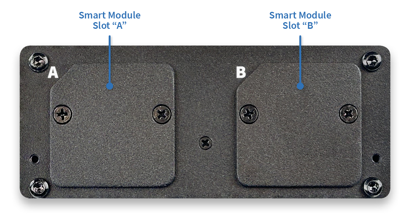
Rear Panel
|
Smart Module Slot “A” or “B” |
There are two module slots on the rear of SmartNode. Each slot may accommodate any of the available Smart Modules, which can add DMX, Station Bus, I/O, Serial, MIDI, and other physical interfaces to the node. |